

Milling or grinding for high precision parts
On Roeders machines, the choice between milling and grinding is made feature by feature, not machine by machine. All machines except the RXP400 can be fully equipped for grinding, so milling and grinding, especially jig grinding, can be combined in a single set-up.
Four criteria decide which process is applied for a machining task:
- the geometry of the workpiece
- the material of the workpiece
- the required precision
- the required surface finish
- 1 set-up: Milling and grinding without re-clamping the workpiece
Where HSC milling reaches the target

Milling is mostly used for roughing, especially in ductile materials like steel, aluminium etc. HSC milling for finishing works with high spindle speeds, small stepovers and low depths of cut. On Roeders machines HSC milling achieves high precision and surface quality directly with the cutter, with precision down to 1 µm and less depending on the application and with surface finishes of up to 0.01 µm. Typical applications are aluminium workpieces which are machined with monocrystalline diamond cutters or hardened steel workpieces milled with very small cutters. But there are also many applications where such tight tolerances and surface finishes cannot be achieved by HSC milling. Then a separate grinding operation is applied.
The CNC control RMS6 processes an NC block in less than 0.1 ms and looks ahead over more than 10,000 blocks, and the drive modules work with a clock frequency of 32 kHz. The RMS6 uses a modern refined spline interpolation with tangential and curvature constant transitions between blocks, so the tool follows the path without abrupt changes of direction that would leave marks on the surface. RACECUT® shortens machining times in 3D machining by up to 20 %.
Typical cases for milling
- Roughing of ductile materials (steel, aluminium, copper etc.)
- Finishing of 3D-contours and freeform surfaces
- Surface requirements the cutter reaches directly, up to 0.01 µm
- Parts made of aluminium, copper or graphite
- (Hardened) steel, carbide and ceramics where tolerance and surface finish allow it
Where grinding is required

Grinding, mostly jig grinding, takes over when roughing by milling is not possible or too expensive due to cutter wear, for example in carbide, ceramics or glass. But grinding is also applied where the tolerance or the surface finish goes beyond what milling holds reliably, especially when achievable tolerances and surface finishes are limited due to the geometry or material of the workpiece or the cutter length. Grinding is very advantageous on workpiece geometries where a line contact of a cylindrical or conical grinding wheel with the workpiece during machining is possible. Then grinding can reach very tight tolerances, sometimes well below 1 µm. It is the process of choice where features have to hold a defined position to one another, as with the bores of a stamping tool or a carbide punch.
In such cases two strategies are available: fast stroke chop grinding, familiar from jig grinding machines, and slow stroke chop grinding with a higher feed rate and multiple passes, which puts less dynamic stress on the machine structure and therefore results in even higher accuracies. For brittle-hard materials such as glass or ceramics, a system for axial ultrasonic excitation of the tool can be fully integrated into the machine.
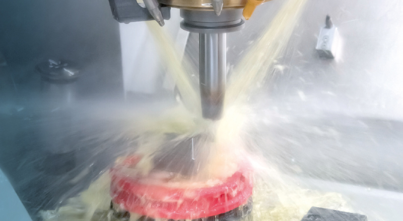
Additionally, grinding is applied on 3D-contours in hardened steel or carbide. With ball-shaped diamond grinding wheels a very small rest material of a few microns only can be taken off the workpiece with a very small stepover. This results in extremely high precision and surface qualities sometimes with Ra values below 10 nm.
Typical cases for grinding
- Roughing of brittle materials like carbide, ceramics or glass
- Centre distances and positional tolerances tighter than milling holds reliably, features where a line contact between tool and workpiece for the cutting process is applied
- Surface finishes well below 0.1 µm also with longer tool lengths
- Glass, ceramics and carbide as well as (hardened) steel
- Bores and precise 2D contours, with conical wheels also for more complex geometries
- 3D-contours in hardened steel for extremely high precision and surface quality
Milling and grinding compared
| Criterion | HSC milling | Grinding (mostly jig grinding) |
|---|---|---|
| Typical role | Roughing in ductile materials, 3D contours, finishing where the cutter reaches the target | Roughing in brittle materials and finishing to final dimension where milling no longer holds the tolerance or surface quality |
| Surface finish | Up to 0.01 µm directly with the cutter with small cutters | Well below 0.1 µm, in parts below 0.01 µm — depending on the application, also with larger tools |
| Materials | (Hardened) steel, carbide, ceramics, aluminium, copper, graphite | (Hardened) steel, carbide, ceramics, glass |
| Typical geometry | 3D contours and freeform surfaces or 2D contours where the tolerances reached are sufficient | Bores, centre distances, roundness, precise 2D contours, 3D contours with special grinding wheels for optical applications |
| Strategy for finishing | High spindle speeds, small stepovers, low depths of cut | Fast stroke or slow stroke chop grinding or 3D grinding with ball nose grinding wheels taking off very little rest material |
| Measurement | Measuring laser for the tool, 3D touch probe for the workpiece | Sound detection for wheel and workpiece contact, 3D touch probe for the workpiece |
Both processes in one set-up
The efficiency gain comes from the set-up, not from the individual process. When milling and grinding run on one machine, the part is clamped once and milled and ground features share the same zero position of the workpiece. There is no offset due to re-clamping of the workpiece between the two operations, and milled 3D contours fit perfectly with ground areas.
For the highest precision with grinding, the final dimension is reached in four steps:
- Grinding the feature with a small allowance: The workpiece is first ground with a small allowance left on it.
- Measure with the 3D touch probe: The allowance actually produced is determined on the machine with the 3D touch probe.
- Calculate the infeed: From the value measured with the 3D touch probe the CNC control RMS6 calculates the exact infeed for a last grinding pass.
- Grind to final dimensions: The machine grinds the workpiece to its final dimensions. No operator intervention is required.
Each measuring device has its task:
- Measuring laser: Measures the tool for milling and carries out the preliminary measurement of the grinding wheel before dressing or measuring it with sound detection.
- 3D touch probe: Measures the workpiece in both processes.
- Sound detection: Measures the grinding wheel on diamond surfaces and detects the contact between wheel and workpiece.
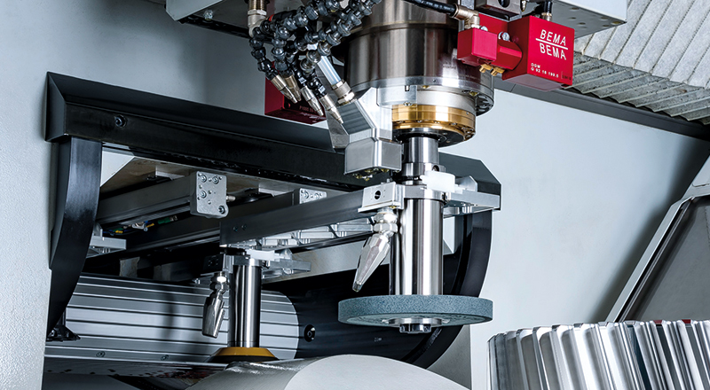
Large grinding wheels can also be used for high precision grinding. A separate tool changer exchanges them automatically, together with the oriented special nozzles that direct the flushing oil to where the grinding process needs it.
What the machine contributes
Precision at this level comes from all components acting together. Roeders develops three of them in-house as one coordinated system: the CNC control RMS6, the drive technology and the machine mechanics. Optical scales resolve the axis positions into the nanometre range, and the solid and heavy portal design of the machine mechanics adds stability. On the RPT series, the NANOTOL® concept provides high-precision guideways and PRECITEMP® technology keeps the machine geometry stable, also during long machining jobs and when the ambient temperature is not constant.
Because control, drives and mechanics come from one source, machines built from 1995 onwards can still receive control updates at low cost — relevant for machines that are in use for up to 30 years or more.
Frequently asked questions about milling and grinding
Neither is better in general. It depends on the geometry and material of the workpiece as well as the required tolerances. HSC milling reaches surface finishes of up to 0.01 µm with small cutters directly and covers 3D contours and a wide range of materials. Grinding, mostly jig grinding, is used where centre distances or roundness need to hold very tight tolerances, sometimes below 1 µm. Grinding can also be the process of choice for surface finishes well below 0.01 µm in larger 3D contours in hardened steel. On Roeders machines both processes can be combined in one set-up, so each feature of the workpiece is finished by the process that suits it.
HSC milling removes material with high spindle speeds, small stepovers and low depths of cut and is used for roughing, 3D contours and 2D contours if the tolerances allow for it. Jig grinding is a process for roughing brittle materials like carbide, ceramics or glass. Jig grinding is also used for producing centre distances to very high accuracy, between bores or between a bore and an edge; roundness is achieved with high precision as well. Jig grinding typically is applied when a line contact between the tool and the workpiece for machining is possible. Small grinding wheels at high rpm produce very precise 2D contours, often bores, and conical wheels are used for more complex applications. Additionally, 3D contours can be ground in hardened steel with very high surface quality below 0.01 µm.
On Roeders machines, milling covers (hardened) steel, carbide, ceramics (only finishing if already sintered), aluminium, copper and graphite. Jig grinding covers (hardened) steel, carbide, ceramics and glass. Hardening is not a precondition for either process.
Yes. All Roeders machines except the RXP400 can be fully equipped for grinding. If there is larger stock on the workpiece and the workpiece is not made of brittle material, the workpiece firstly is roughed by milling and finished by grinding in a single set-up, so no offset due to re-clamping of the workpiece occurs between the two operations and the remaining stock for grinding can be kept very low. This results in short machining times also for high precision. For brittle workpieces (made of carbide, ceramics or glass) it is vice versa, roughing is made by grinding, but where the geometry of the workpiece requires it final contours are milled.
The workpiece is ground with a small allowance and measured with the 3D touch probe. The CNC control RMS6 calculates the exact infeed for a last grinding pass from the measured allowance, and the machine then grinds to the final dimensions without operator intervention.
Achievable accuracy depends on the geometry of the workpiece, the material and the process, so for the technology in general only target ranges can be given: high precision, sometimes in the submicron range, is achieved through milling with small cutters or grinding. For example a mould for small lenses for mobile phones can be milled with a roundness of 0.5 µm. However, for larger workpieces like a stamping die such kind of tolerance is not reached by milling. If a tolerance below 1 µm is required grinding is the process to be chosen. Concrete values are demonstrated by a test cut on the customer’s own sample part before purchase.